In this chapter the application of the BuildingSystems library for multi-zone building modeling is demonstrated.
For this purpose, a thermal building model of the Thermal Model House (http://www.thermisches-modellhaus.de) with
two thermal zones shall be created:
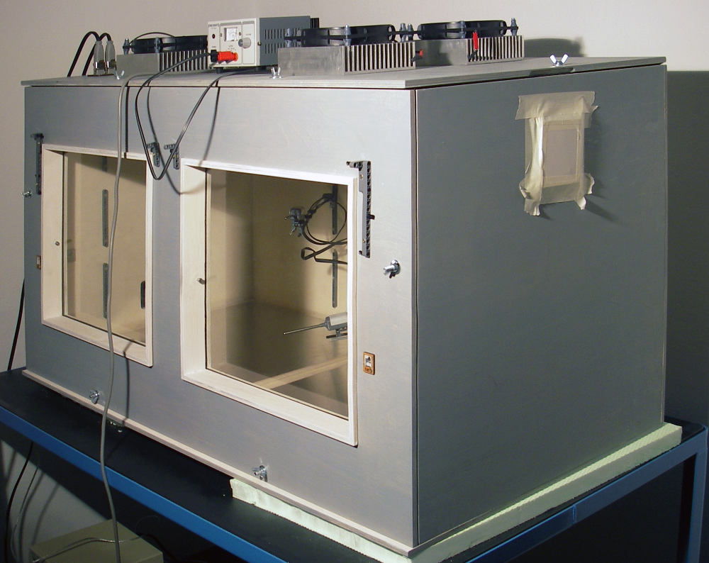
Thermal Model house: A portable experimental test facility for building physics studies, developed by UdK Berlin.
The Thermal Model House (TMH) is a portable experimental test facility with a simple geometry and a compact size
of approximately 1 m length, 0.5 m depth and 0.5 m height. This small thermal box is able to reproduce
different phenomena of building climatization within physical experiments. Due to its manifold configuration
options, it is possible to do experiments about the energy balance of rooms, about the heat and air transport processes within
rooms, about ventilation, heating and cooling of buildings as well as about building control.
The TMH is being developed at the Institute of Architecture and Urban Planning at UdK Berlin.
It is used for the education of architecture and engineering students and also for research.
One configuration of the TMH works with a inner partition wall, which divides the air volume of the
box into two different thermal zones. These zones can be separately heated or cooled using individual
heating surfaces on the bottom and cooling surfaces on the ceiling. Exactly this configuration
shall be modelled in the present case.
The modelling and simulation process is described using the Modelica simulation environment, Dymola (version Dymola 2018 FD01).
First of all the Modelica library BuildingSystems has to be loaded into Dymola. After that, the library
will occur in the library tree in addition to the other present Modelica libraries.
The creation and configuration of a new thermal building model takes place in the following steps:
Configuration of the building model structure (topology of the construction of the buildings model)
Definition of the building model parameters (building geometry and physical parameters of the construction elements)
Definition of the boundary conditions of the system model (climate conditions of the building ambience, set temperatures for heating and cooling for each thermal zone)
Create a new package for your simulation experiment.
Open dialog: File -> New -> Package and fill in the field Name of new package: “ThermalModelHouse” and click OK
Mark the new package ThermalModelHouse in the package browser and save it with File -> Save in the file ThermalModelHouse.mo in a folder of your choice.
Create a new building model based on the template model class BuildingTemplate. That means you insert a new building model into the previously defined package as follows:
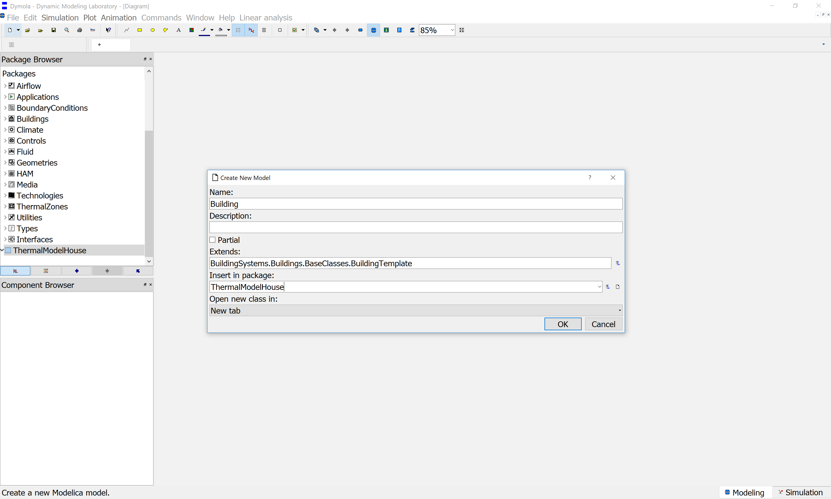
Definition of a building model based on a building template
Open dialog: File -> New -> Model and fill in the field Name of new model: “Building”. Then
click on the button to the right of the field Extends (optional): and navigate to the model class
BuildingSystems.Buildings.BaseClasses.BuildingTemplate and click OK. Further click on the button right of the field
Insert in Package (optional): and navigate to the package ThermalModelHouse on the top level and click OK (compare the Dymola screenshoot above).
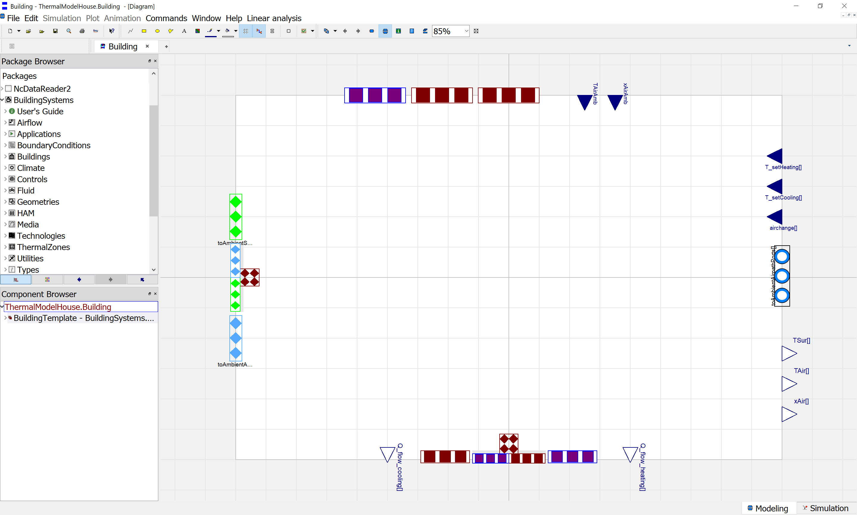
As a result you can see now the inner structure (the Diagram view in Dymola) of the empty building model.
On the left side you see the interfaces to the building ambience, below the interfaces to the ground of the building and on
the right side the input signals for the set temperatures for heating and cooling of each zone and the interfaces of the air
paths to the ambience.
Instantiate two thermal zones, which shall represent the left and right part of the TMH.
For this purpose drag and drop a component model from the class BuildingSystems.Buildings.Zones.ZoneTemplateAirvolumeMixed
into the building model and rename it to zone1. Add zone2 in the same manner:
For the opaque constructions (walls, bottoms, ceilings etc.) use the model class
BuildingSystems.Buildings.Constructions.Walls.WallThermal1DNodes and for the transparent constructions (windows) the model class
BuildingSystems.Buildings.Constructions.Windows.Window.
Notice, that each component comes with a blue line (which indicates side 1)
and has the connector toSurfacePort_1. The other unmarked side 2 owns the connector toSurfacePort_2.
The blue line helps you to distinguish both component sides, e.g. if you want to define single layers of a construction
in a certain order. In our case we bring all component models in a position, that all blue lines
show to the zones respectively in the case of the partition wall to zone1 and to the adjacent zone2.
In our case we have to instantiate seven walls (wall1 to wall7), two bottoms (bottom1 and bottom2), two ceilings (ceiling1 and ceiling2)
and two windows models (window1 and window2).
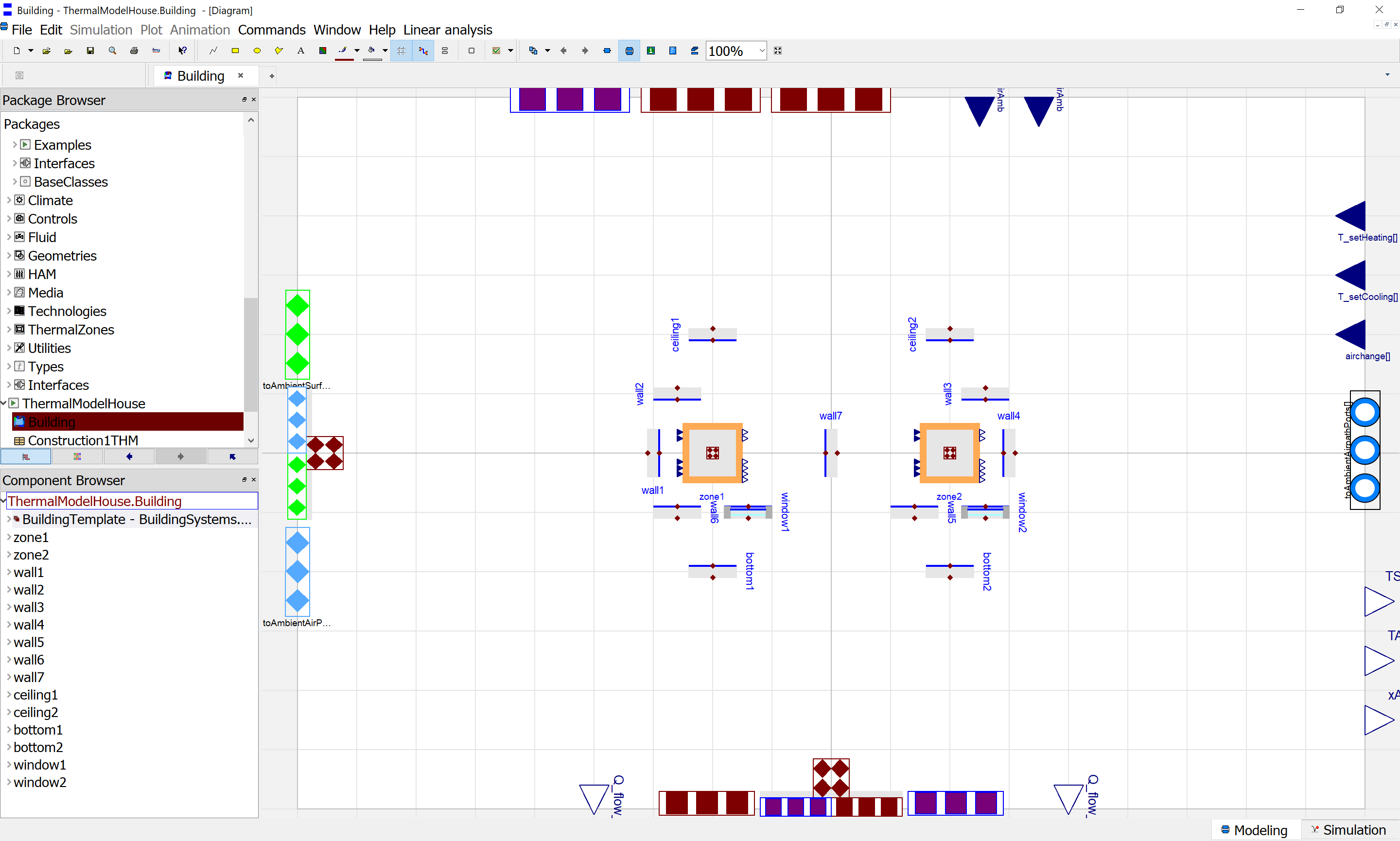
Connect construction elements.
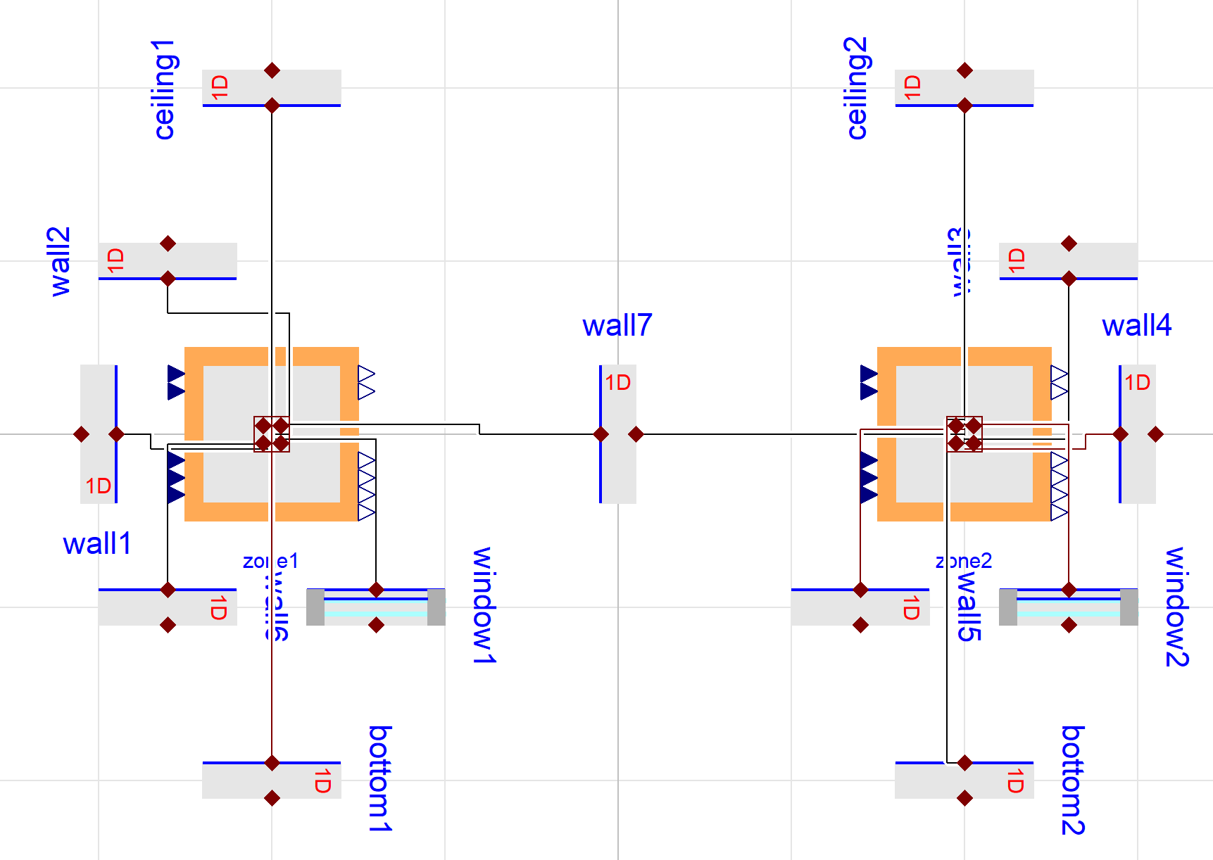
Now connect the connectors of all “blue sides” with the zone models as in the following picture:
Building model with connected construction elements
Here each zone model offers you six different positions for connections to the construction elements (toConstructionPorts1 to toConstructionPorts6)
to enable a simplification of the graphical diagram.
In a further step connect the connectors of the other sides of all construction elements to the construction connector of the building model (toConstructionPorts on the left side).
Finally connect the input values of T_setHeating and T_setCooling (four connections) and the output values
Q_flow_heating and Q_flow_cooling (again four connections) from the building model to both zone models.
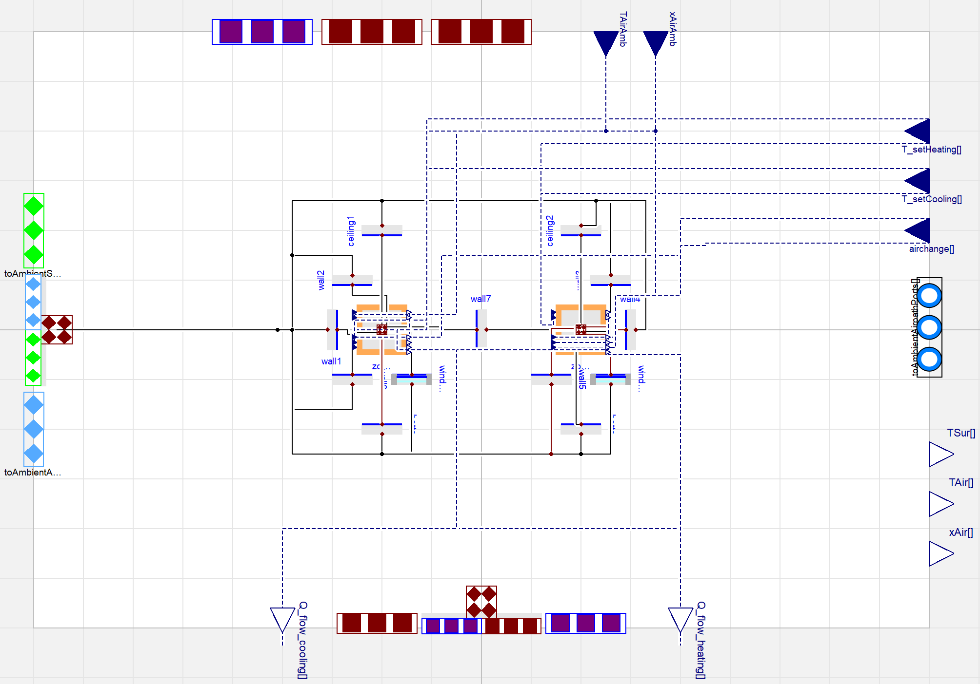
Now your topology of your building model is completely specified:
Completed topology of the building model with two thermal zones
Now the building model has to be completed with parameters, which exactly describe the problem. The first type are geometrical parameters,
e.g. the size of the construction elements or the volumes of the zones. The second type are physical parameters which define the building constructions
(e.g. the heat conductivity or specific heat capacity of the used materials).
Geometrical parameters
The TMH has a strongly simplified geometry. In our problem each thermal zone describes one half of the TMH, which has in total an inner dimension
of 1.0 m x 0.5 m x 0.5 m. So each opaque construction element (walls, bottoms and ceilings) has a height of 0.5 m and a width of 0.5 m.
Double-click on each component and fill in these values in the General tab in the Geometry group.
Both thermal zones have an air volume of 0.5 m x 0.5 m x 0.5 m = 0.125 m3. The height of the zone is 0.5 m.
Fill in these values into the zone model’s zone1 and zone2.
Each of the windows of the TMH has a width of 0.378 m and a height of 0.33 m, which leads to a window area of approx. 0.125 m2.
The thickness of the window pane is 0.003 m. Assign these three values to both window models.
Because window1 is enclosed in wall6 and window2 in wall5 the area of the window models has to be communicated from the window to the wall models.
Double-click on wall6 and fill in the parameter field nInnSur 1 and in the field AInnSur using the Edit Text option
AInnSur=window1.width*window1.height
Do the same with wall5 and window2.
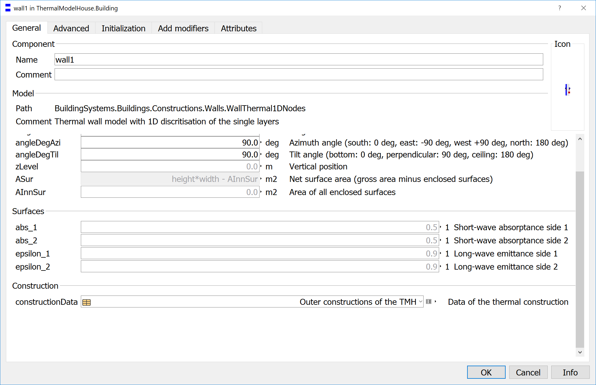
Finally add the parameter values for the orientation of each construction elements, which face to the ambience by setting the azimuth angle
and the tilt angle. The default values for each construction element (walls and windows are 90.0 degree for the tilt angle and 0.0 degree
for the azimuth angle. North is defined by an azimuth angle of 180 degree, east by -90 degree and west by + 90 degree:
element
angleAzi
angleTil
element
angleAzi
angleTil
wall1
90.0
90.0
bottom1
0.0
180.0
wall2
180.0
90.0
bottom2
0.0
180.0
wall3
180.0
90.0
ceiling1
0.0
0.0
wall4
-90.0
90.0
ceiling2
0.0
0.0
wall5
0.0
90.0
window1
0.0
90.0
wall6
0.0
90.0
window2
0.0
90.0
wall7
default
default
Construction parameters
All the opaque construction elements except the partition element wall7 share the same construction.
For this reason a common construction type shall be configured, which will be later assigned
to each individual construction.
Definition of a construction type
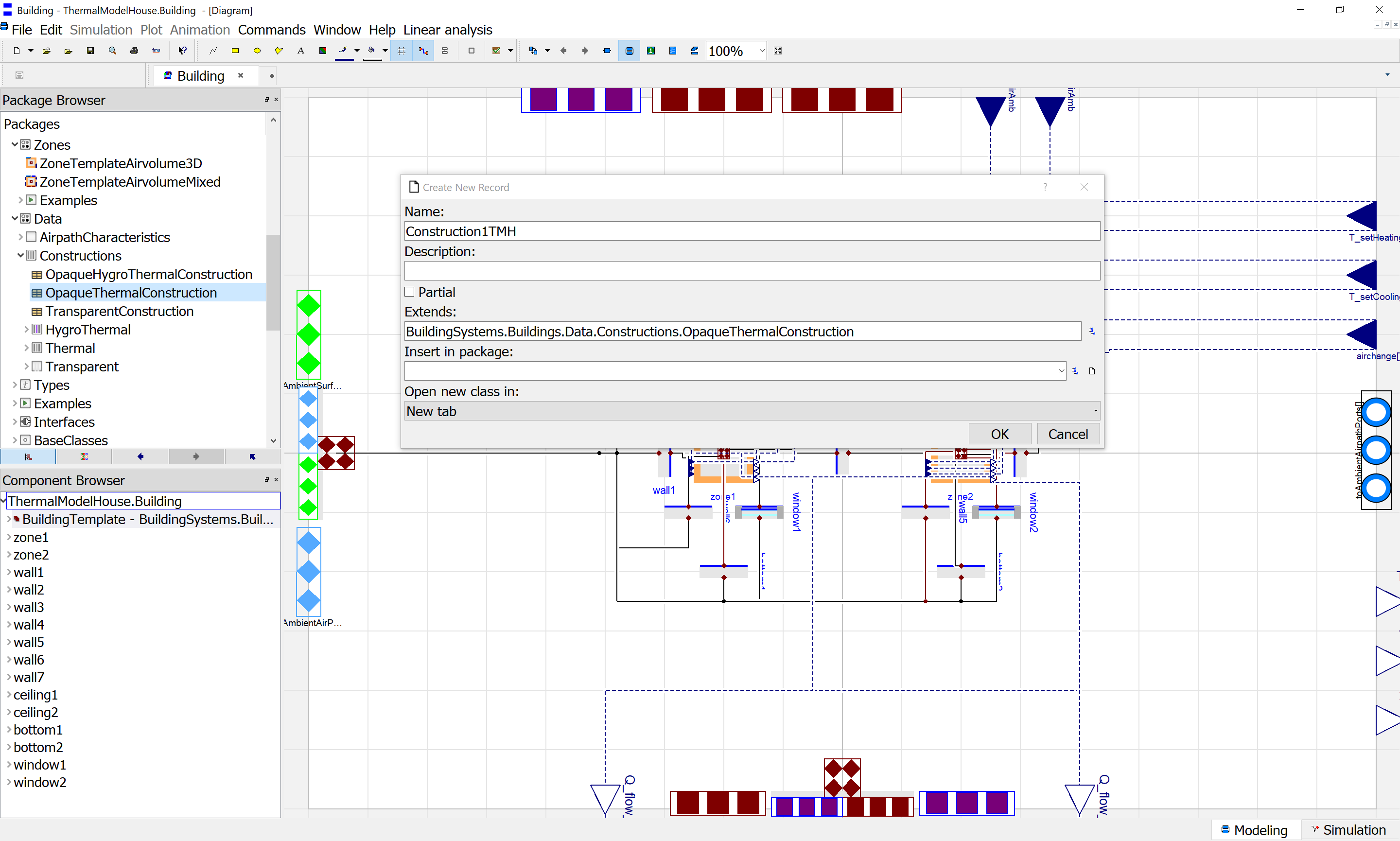
Extend a child record from the general parent record for opaque constructions
BuildingSystems.Buildings.Data.Constructions.OpaqueThermalConstruction and rename it to Construction1TMH. Then
include it in the package ThermalModelHouse.
Definition of a construction type based on template for opaque constructions
The Construction1TMH shall have three layers. The materials of the three layers are 0.006 m wood, 0.030 m insulation
and again 0.009 m wood. The layer order is counted from inside (zone) to outside (building ambience). The
BuildingSystems library contains in the package BuildingSystems.HAM.Data.MaterialProperties
a database with pre-defined thermal and hygro-thermal material property sets.
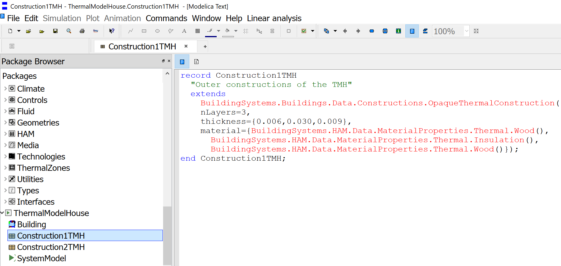
Now double-click on the construction type record Construction1TMH left in the package browser and adapt the parameterization
of the construction direct in the Modelica source code editor of Dymola with the help of the pre-defined materials:
recordConstruction1TMH"Outer constructions of the TMH"extendsBuildingSystems.Buildings.Data.Constructions.OpaqueThermalConstruction(nLayers=3,thickness={0.006,0.030,0.009},material={BuildingSystems.HAM.Data.MaterialProperties.Thermal.Wood(),BuildingSystems.HAM.Data.MaterialProperties.Thermal.Insulation(),BuildingSystems.HAM.Data.MaterialProperties.Thermal.Wood()});endConstruction1TMH;
Assignment of an construction type
Now you can assign this common construction type to all the opaque construction elements by inserting
component references using the component parameter dialog of Dymola:
The generated code, for example for wall1 shall look now like:
Create in the same manner for the partition wall a second construction2TMH,
which only consists in one layer of wood with a thickness of 0.009 m and assign it afterwards to wall7.
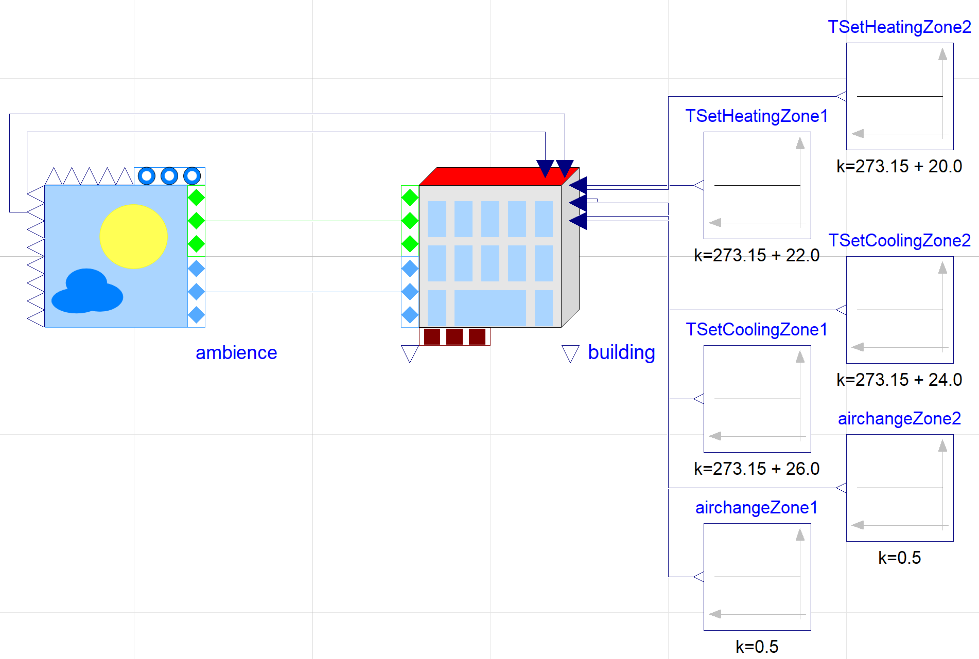
3.3. Configure the system model and set its boundary conditions
Create a new model with the name SystemModel and insert it into the package ThermalModelHouse.
Instantiate the previous defined building model within the system model and rename it to building.
Instantiate an ambient model BuildingSystems.Buildings.Ambience within the system model and set the climate data
(parameter weatherDataFile) to USA_SanFrancisco_Meteonorm_ASCII.
Assign the parameter nSurfaces of the ambient model to the number of surfaces of the building, which are in contact
with the building environment:
nSurfaces={building.nSurfacesAmbience)
Connect the ambient model and the building model regarding to their blue interfaces (boundary conditions of the facade surfaces to the air)
and their green interfaces (boundary conditions of the facade surfaces to the solar irradiation and other enclosing surfaces)
Connect the output variable ambience.TAirRef and the input variable building.TAirAmb (ambient temperature at
a reference height of 10 m) and also ambience.xAirRef and building.xAirAmb (ambient absolute moisture).
Add six constant sources of the type Modelica.Blocks.Sources.Constant for the definition of
the set temperatures for heating and cooling as well as the air change for both thermal zones: